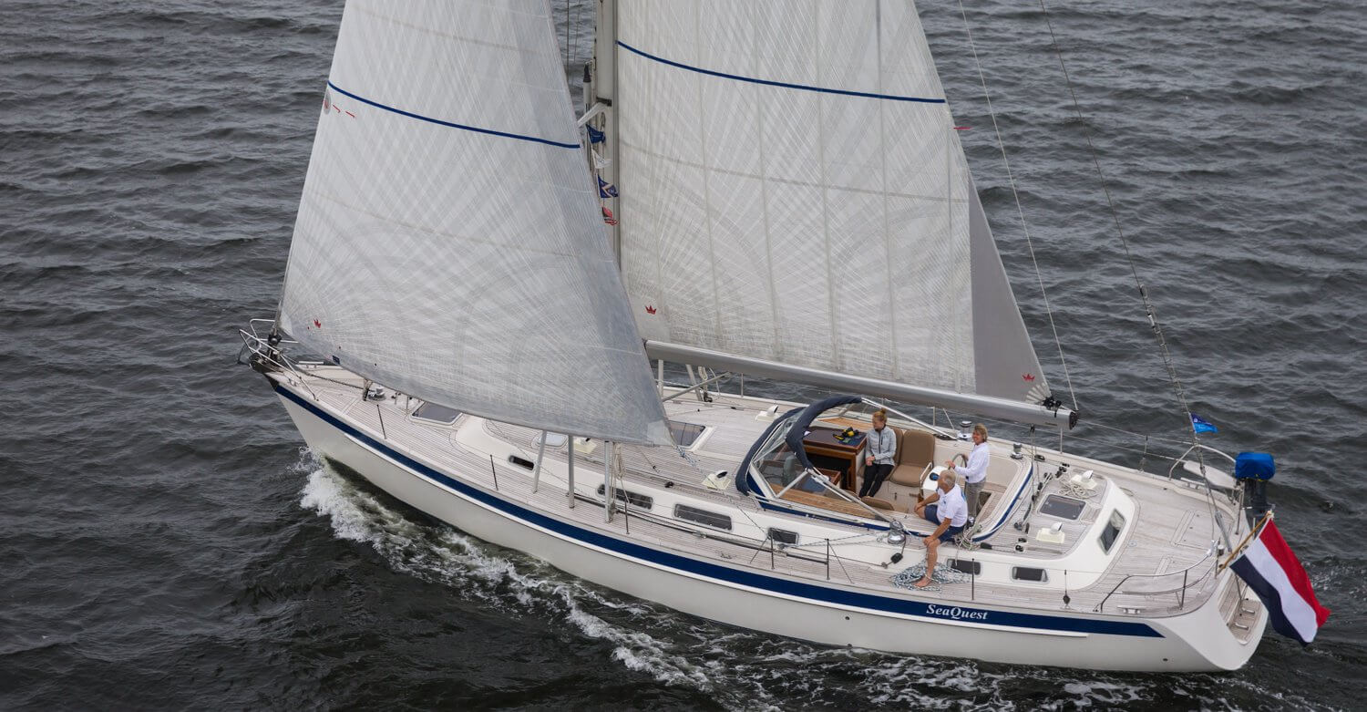
The SeaQuest is a 2007 Hallberg-Rassy 48 with construction number 38. We are the second owner since April 2014. Before this we had the Brandaan for 8 years, a Hallberg-Rassy 40 from 2004 also with construction number 38.
Hallberg-Rassy's are fantastic for long distance sailing with a nice combination of safety, comfort, easy to sail and a luxurious and tough look. Because of the design and the weight (the SeaQuest weighs about 25 tons) the seagoing is very stable, and also quite fast. The centre cockpit provides a secure feeling, also because we can do all the handling of the sails within the cockpit.
The interior layout is beautiful with lots of wood, comfortable with good beds, sofa and chairs, and in many details suitable for use in heavier seas. Think of all the grips in many places, a kitchen where you can stand well 'fixed' and all floors equal without annoying steps.
We bought the SeaQuest to enjoy sailing in Zeeland and Northern Europe with growing girls. But also to live on it with the two of us and to take a longer sailing trip when we retire early.
The SeaQuest has a furling mainsail, a genoa, a genaker and a cutter jib. That cutter jib is not always handy when we have to tack on the Grevelingen or the Oosterschelde with lighter winds. Then we have to furl the genoa before we can tack 😂, but we take that for granted. At sea with heavy seas and stronger winds we are only too happy with it. The furling mainsail is very practical because it is very easy to reef. We use the new furling genaker much more often than the previous one. On a downwind course we soon set the sails in butterfly position with the genoa on the boom. That sails very comfortably.
Classification SeaQuest
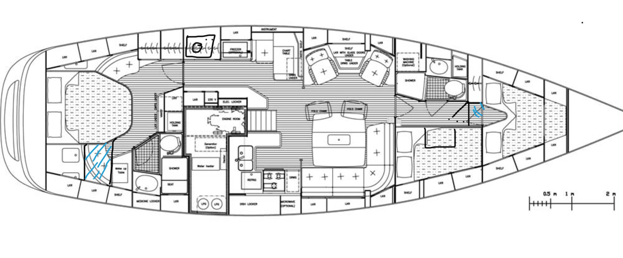
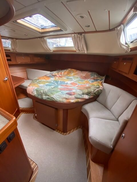
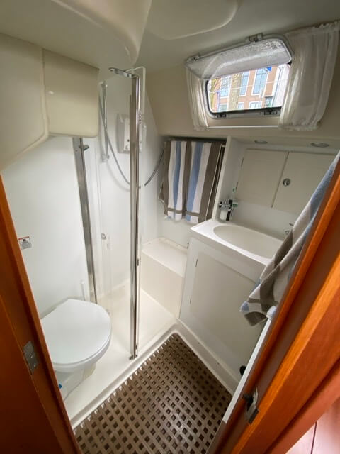
The layout of the SeaQuest is shown on the picture below. With a center bed in the back and a good workplace for Mira. It is a nice spacious cabin with a private bathroom and lots of closet space.
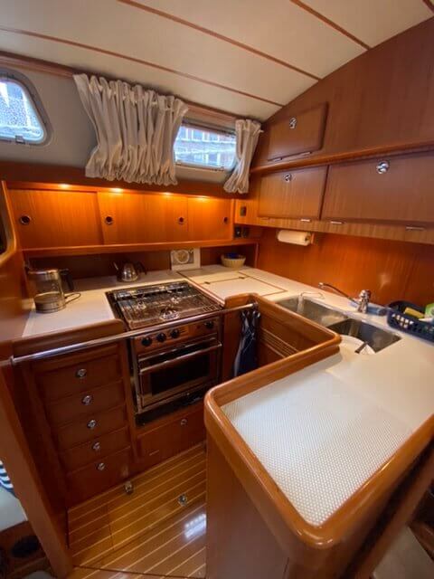
In the cabin the kitchen is right on the starboard side next to the entrance. In the cabin itself is a spacious table with around a sofa and two lovely chairs.
The girls each have their own cabin in the front. Marinthe sleeps in the supercabin where Toine's workplace is. Eline sleeps in the front cabin.
Below you can click on the floor plan for a picture of the room in question.
Rear cabin
Bathroom behind
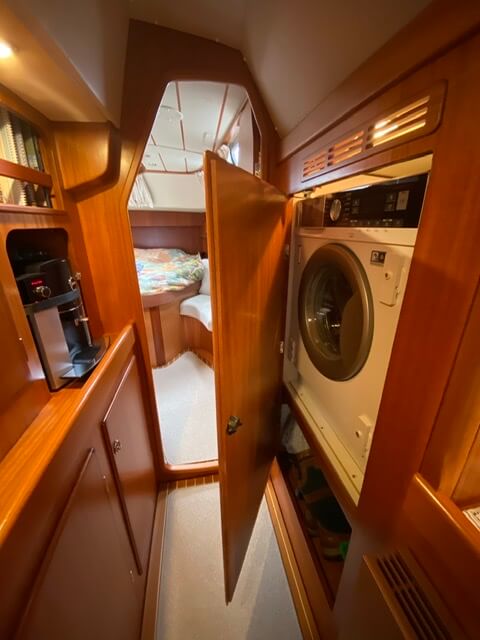
Hallway to aft cabin
Kitchen
Maps table
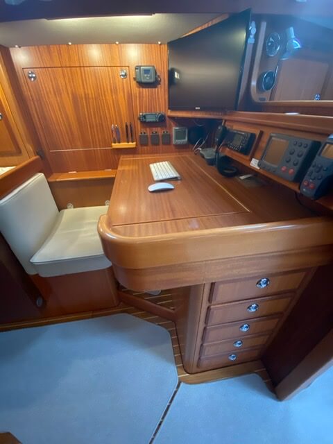
Cabin - seat
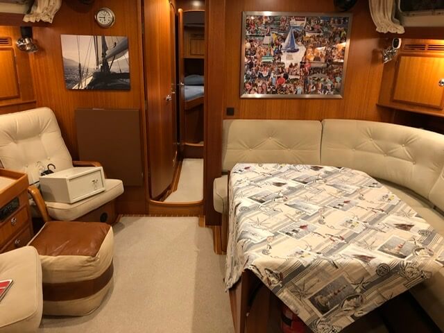
Supercabin
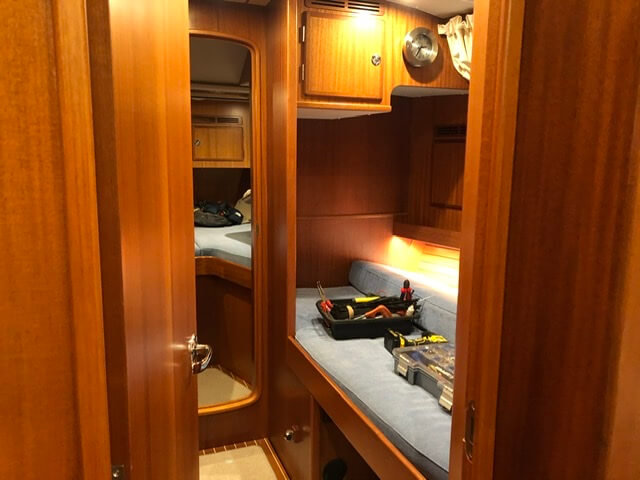
Hut Eline
Bathroom for
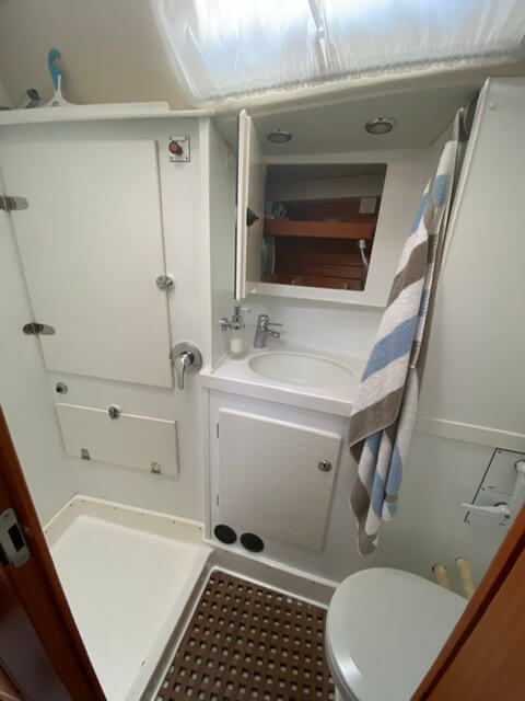
Specifications
Length: 14.99m
Width: 4.50 m
Draft: 2.34 m
Mast height: 21.75 m
water tank: 910 litres
diesel tank: 800 litres
anchor: Uktra 35 kg
chain length: 110 m
Engine: Volvo Penta D3-110, 81 KW/110 HP
Navigation
The SeaQuest has a complex network for navigation equipment. This is due to the amount of devices in combination with the different ages of these devices. We prefer to renew the network only for parts where necessary, especially if the older parts are still performing well.
Since buying the SeaQuest, Toine has built this network step by step. Also because the previous owner had a lightning strike which caused part of the network to be repaired by an Italian shipyard. "Prutswerk" according to Toine 😎.
We can both operate the navigation equipment very well, however so far I have not studied how that is technically set up behind the screens. That's Toine's area of expertise. Actually, it's good to know something about it; for me it works well to write a blog in my own words. I learn a lot from this and it's fun to do 😊.
On the SeaQuest, the navigation equipment is all Raymarine's. The following items of equipment are installed in the cockpit outside:
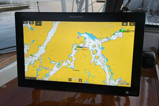
- Navigation computer with touchscreen (Axiom XL 16) - on the chart sheet to the left of the cabin entrance.
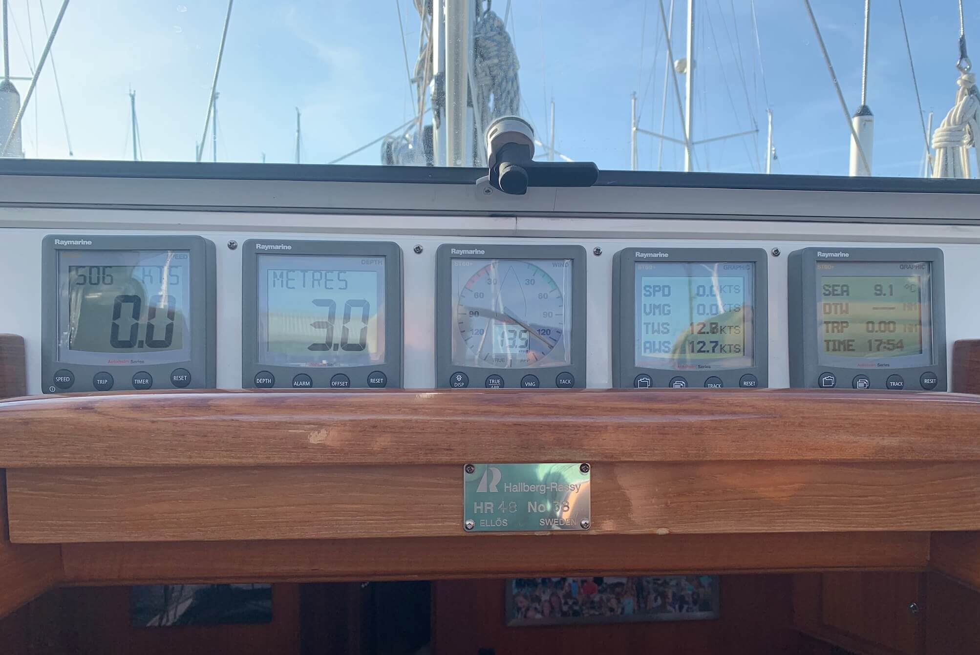
- Depth gauge.
- Speed gauge.
- Wind gauge.
- Two variable meters freely adjustable with boat information such as speed, wind, seawater temperature, time etc.
These five meters are installed next to each other above the cabin entrance.
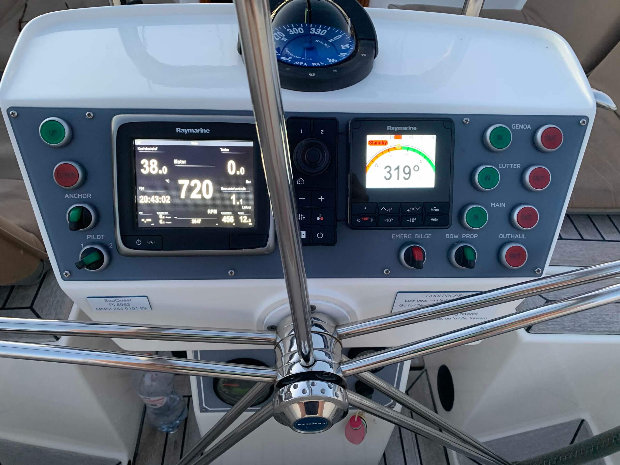
The following units are on the steering position:
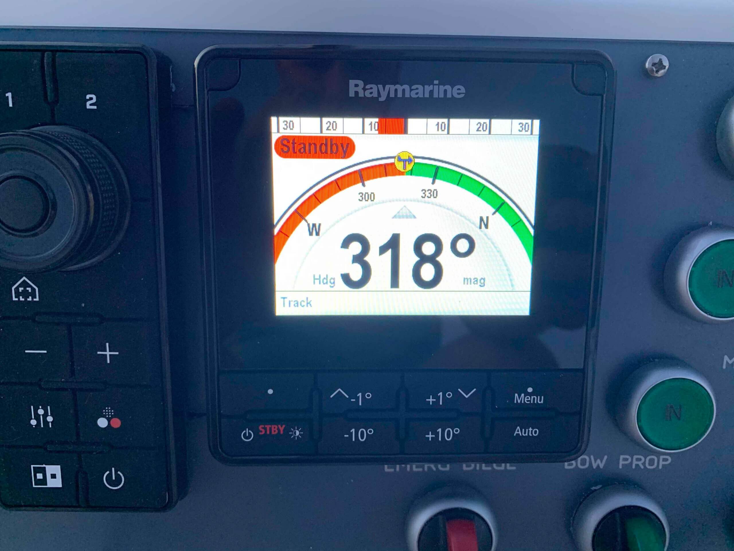
- Control panel for the autopilot (top right).
- Control panel for the thermal camera (center).
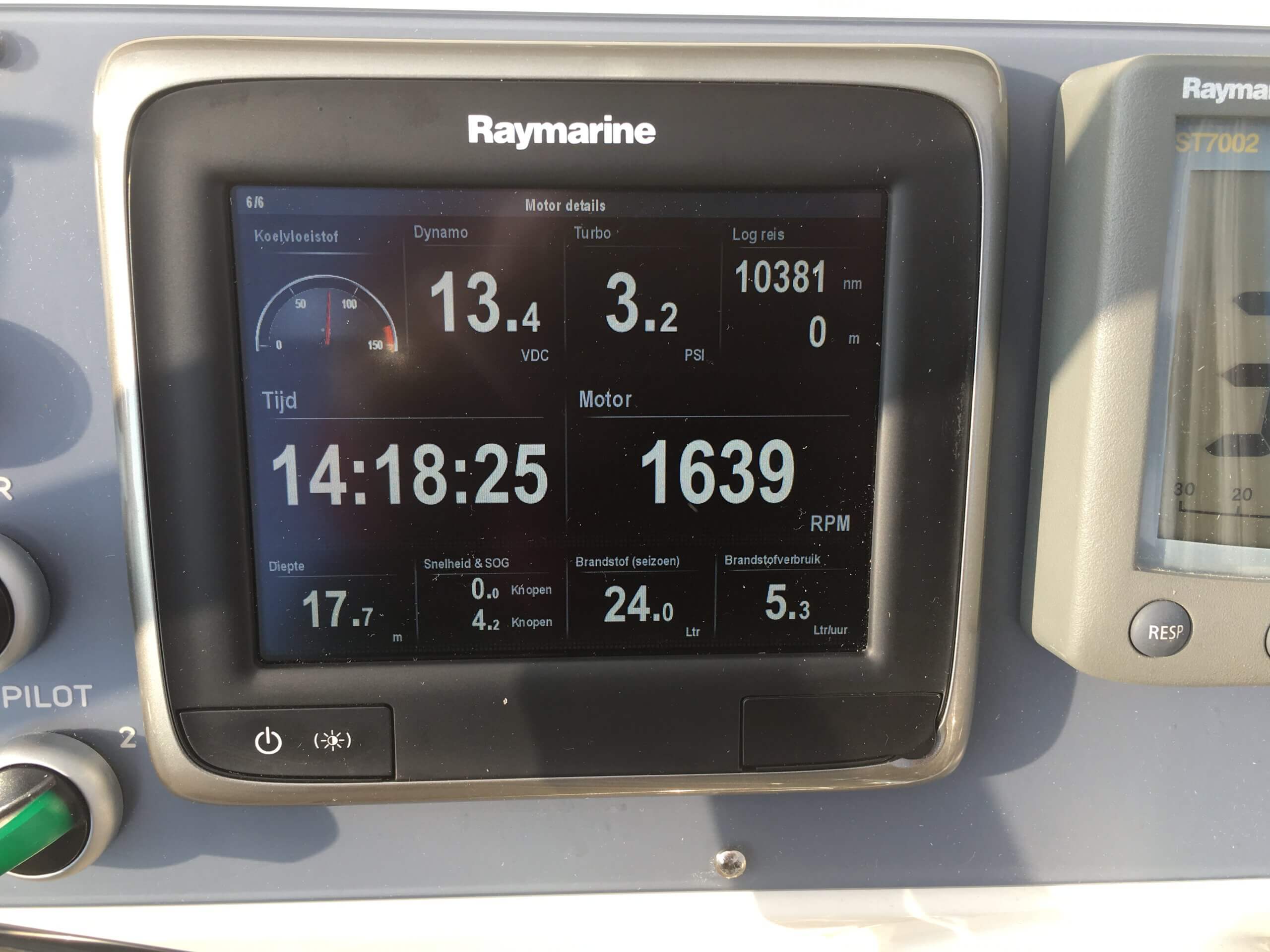
- Second navigation computer with smaller screen (A67) (top left).
We use the A67 primarily for easily visible display of engine information (consumption, RPM, battery charge capacity, temperature and turbo pressure). In addition, it is a complete backup for the Axiom XL 16.
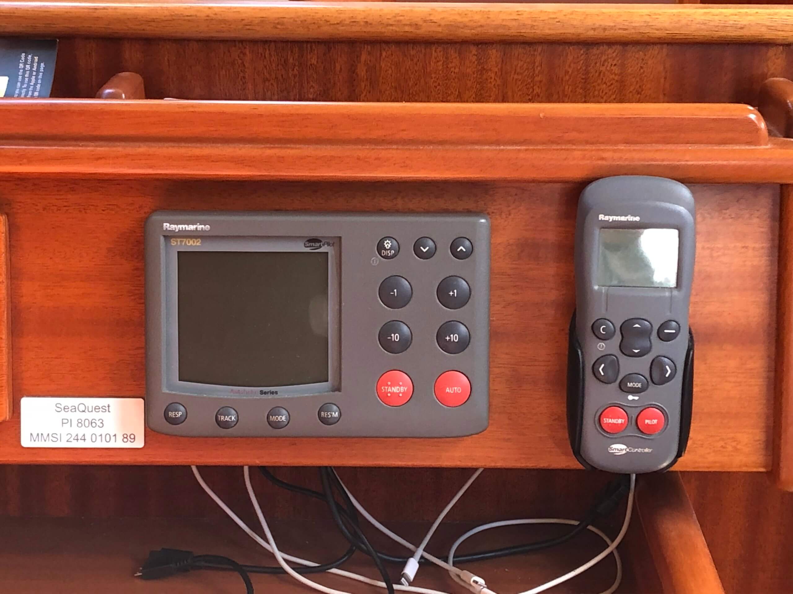
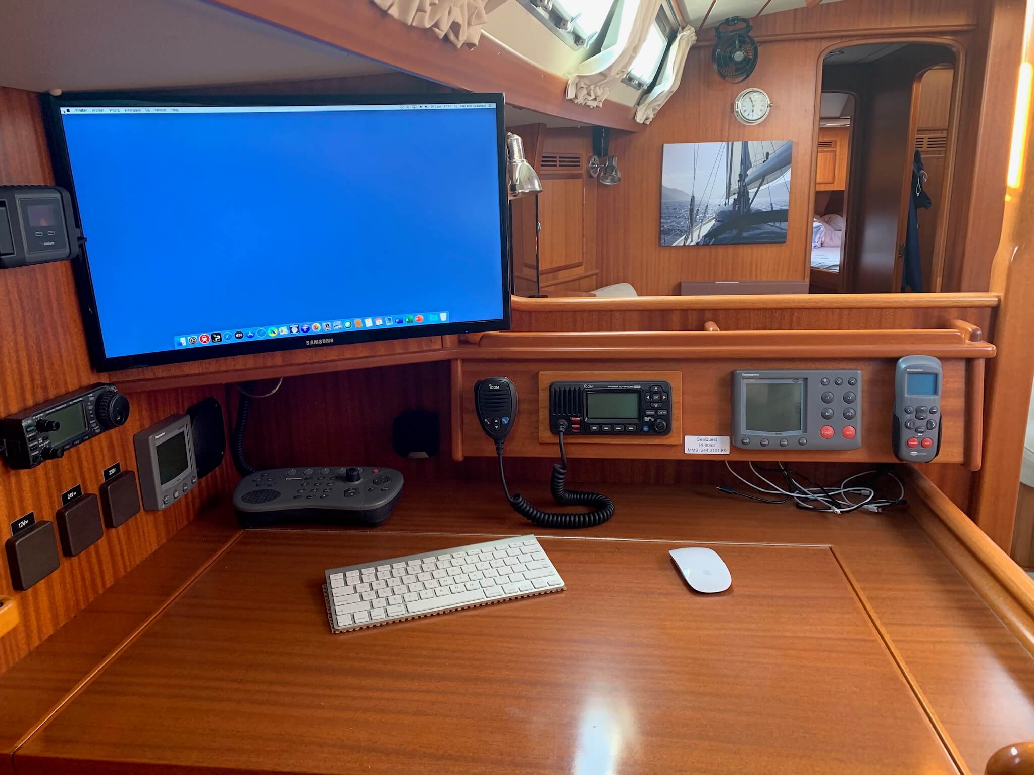
The following units are installed inside close to the card table:
- Controls for the autopilot (when we're navigating inside and as backup for those on the steering position).
- On the left next to it, a variable gauge for speed, depth or wind data (because otherwise an ugly hole in the wood is visible).
- Navigation screen as repeater of the Axiom XL 16.
- Control buttons for the Axiom XL 16 (because we don't have a touchscreen inside).
- Charger of the remote control to operate the autopilot.
In this way, we can also perform navigation entirely from inside.
Halfway up the mast is the radar, at the top of the mast is the antenna for VHF and AIS reception, and on the first spreader is the thermal camera.
In the aft cabin are the two autopilot systems. Autopilot 1 (EVO-400) with a mamba drive and autopilot 2 (EVO-400) with a linear drive. On the helm is a selection button to set one of the two pilots.
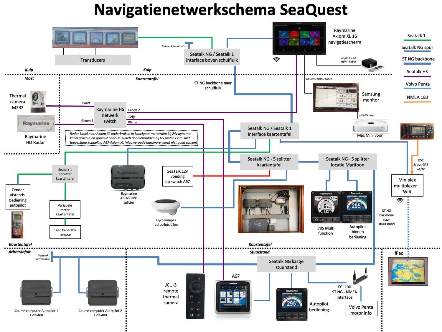
How all these devices are linked together in the navigation network is shown in the diagram below.
The Axiom XL 16 in combination with autopilot 2 is our main navigation component. On the map of the Axiom XL 16, we see our position and course, plot routes with waypoints, and let the autopilot steer to a waypoint in "track" mode. We also see on that map the AIS triangles of other ships around us. We also show the radar images on it, either over the map or as a separate radar screen next to the map. By now we can read and write with this device and could hardly do without it. We can also receive the technical camera on it.
So as a backup to the Axiom XL 16, we have the A67 at the helm and also the Mac Mini (at the chart table) and two iPads. This has iNavX on it and because we can transmit the full board information via the miniplex to those Apple devices, we also have our position and course on the chart there, AIS of ships around us, data on speed, wind strength/direction etc. That also makes that a complete navigation tool. Also, the A67 transmits a wifi signal that allows us to see and control the A67 screen on the iPads via the Raymarine app. That is sometimes easy to have a screen next to the Axiom XL 16 with some additional information or for those inside during a night sail through to briefly check the situation.
All these devices are in the on-board network that consists of 3 different Seatalk networks (Seatalk 1, Seatalk NG and Seatalk HS).
Seatalk NG (new generation) is the main network. That runs via a backbone through the boat (thick blue line in the network diagram above), starting at the five meters above the cabin entrance, through the chart table and steering position to the aft cabin. Seatalk NG is where most of the devices are connected. Seatalk 1 and Seatalk 2 are for the older devices, and are connected to Seatalk NG via an interface. Seatalk 1 is needed for the gauges above the cabin entrance and for the autopilot remote control transmitter.
The Seatalk HS (high speed) network is separate from the other Seatalk networks and feeds through the HS switch the thermal camera controls, radar and thermal camera images on the Axiom XL 16 and the A67, and through the miniplex on the Mac Mini and iPads.
The network box behind the five gauges above the cabin entrance has connectors for 1) the start of the NG backbone, 2) the interface between Seatalk 1 and Seatalk NG, 3) the connection to the Axiom XL 16 navigation screen, and 4) the NG backbone to the chart table.
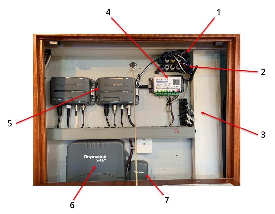
In the small cabinet next to the chart table are the following components (see the picture above):
- Network connector block with connectors for 1) NG backbone from the box above the cabin entrance, 2) 12v power supply for the Seatalk networks, 3) coupling with Seatalk 1 network box at the card table (nr 3 in the picture), 4) coupling with the keyboard at the card table and 5) NG backbone to the box underneath (nr 2 in the picture).
- Network connectorblock with connectors for 1) NG backbone to the box above (no. 1 in the picture), 2) connection to the AIS (no. 5 in the picture), connection to the miniplex and 4) NG backbone to the steering position.
- Seatalk 1 network cabinet with connectors for connecting to 1) the Seatalk NG network, 2) the remote control transmitter for the autopilots, 3) variable meter card table and 4) control autopilots.
- Miniplex for wifi connection to iPads and Mac Mini.
- The AIS devices. On the right is the splitter for splitting the antenna signal to AIS and VHF. The connectors underneath are from left to right for 1) 24v power supply, 2) coupling with the marine radio, 3) coupling with the AIS device on the left and 4) coupling with the antenna. On the left is the AIS device for receiving AIS signals from other boats and sending our own AIS signal. The connectors below are from left to right for 1) 24v power supply, 2) coupling with Seatalk NG, 3) coupling with the AIS antenna in the ceiling near the chart table and 4) coupling with the splitter.
- Seatalk HS network switch (for distributing radar and thermal camera images).
- Antenna box for the remote control of the autopilot.
The network connector block in the steering position has connectors for 1) NG backbone from the card table, 2) receiving the engine information, 3) operating the autopilot in the steering position and 4) NG backbone to the aft cabin.
The network box in the aft cabin has connectors for 1) NG backbone from the helm station, 2) link to autopilot 1 and 2 (EVO-400), 3) link to the gyro compass for autopilot 2 and 4) NG backbone end.
Electricity
Toine has made a very nice electricity scheme of the whole circuit of the boat. In recent years he has adapted and organized this circuit to his own wishes. He keeps track of every change.
The power consumers on the boat get their power from three different circuits, each with its own voltage: 220v, 24v or 12v.
The 220v circuit feeds the power sockets, the battery charger for charging the batteries, the boiler, the radiator heater, the water maker pump and the washing machine. Pictured by the green lines in the illustration below.
The 24v circuit feeds the autopilot, the navigation system, the inside and outside lights, the electric winches, the iridium-GO, the fridge and freezer, the electric toilets, various pumps, the inverter (24v -> 220v), the inverter (24v -> 12v), the bow thruster, the hydraulics for rolling the sail in and out, the anchor winch, the hot air heating, the thermal camera and the water maker boost pump. Via the 24v switch panel we can also switch on the 220v heater for the radiators. Pictured by the blue lines in the illustration below.
The 12v circuit feeds the VHF radio, the gas button (safety valve of the gas system), the short wave radio, the A67 navigation screen on the steering position, the Seatalk navigation board network and the air blowers in the heating radiators. These are the yellow lines in the picture below.
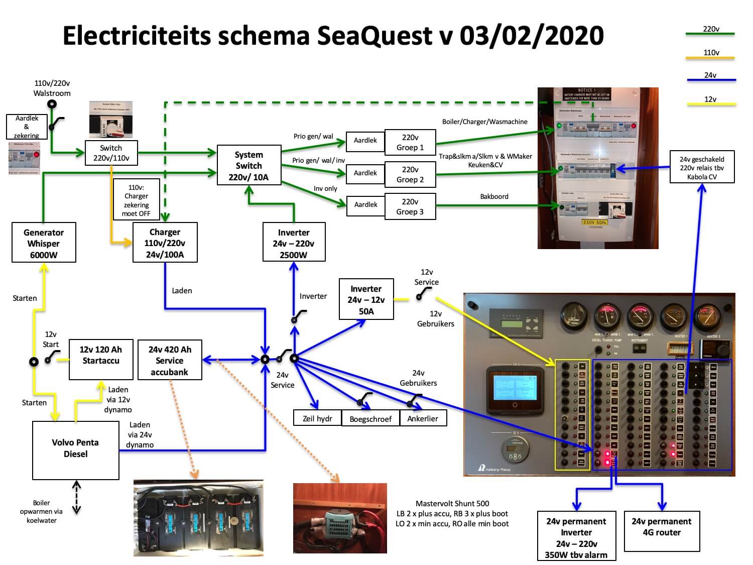
We can get power for the 220v circuit in three ways:
- Via shore power - only if we are in a port - delivers 220v directly.
- The generator - which runs on diesel - delivers 220v directly.
- Via the 24v battery bank and the inverter (which converts power from the 24v batteries to 220v).
There are three 220v electricity groups and an intelligent tool called the System Switch regulates which groups get power:
- Group 1 is used for the boiler, the battery charger and the washing machine - these are the heavier appliances - which only gets power when we are connected to shore power or when the generator is running.
- Group 2 is for the water maker pump, the heating and the sockets (except the sockets on the port side of the cabin) - which gets power when we are connected to shore power, via the generator or via the inverter (24v -> 220v).
- Group 3 is for the sockets on the port side of the cabin - these are used for sensitive devices such as the computer that have difficulty with switching the Switch - it only receives power via the inverter (24v -> 220v).
The green lights on the panel indicate which group is powered.
When we are connected to 110v shore power (is so in the USA, Canada and Asia) only the batteries are charged. Then the switch on the panel must be set to 110v (is now standard on 220v). The 220v groups are then powered via the generator or inverter and not directly via shore power. The Systems Switch can't handle 110v (we know from our own experience when we were in Florida 😉).
The 24v batteries can be charged in three ways:
- When the engine is running - it directly charges the 24v batteries - and also the 12v starter battery (which is only used for starting the engine and the generator).
- When the generator is running - it supplies 220v via the System Switch to group 1 which the battery charger is in.
- Through shore power - on 220v via the System Switch to the battery charger in group 1, on 110v directly to the battery charger.
When sailing for longer distances it is important to have enough diesel on board to get power via the engine or the generator, in addition to the wind for the sailing itself.
Alternatives to diesel are solar panels, a wind generator or a water generator. We had a wind generator on the Brandaan, but it delivers relatively little power (only on close reach or beam reach course), makes annoying noise, and is far out of balance for the power consumption on the SeaQuest. A water generator produces a lot more power and is interesting for us. It is on our list. Solar panels do a bit, but not enough for our total consumption and only useful in sunny places.
